Or The Curious Case of the Disappearing Hole
Recently I encountered a problem with some VectorDrawable which caused much head scratching but there turned out to have a logical explanation and really quite straightforward fix. However my initial bafflement before realising the cause of the problem makes me think that others may encounter similar issues, hence writing this post.
The problem because apparent when I received some SVG assets from on of the designers on my current project (I’m under NDA so cannot elaborate, I’m afraid). One asset had a cutout topologically equivalent to this graphic:
What we have here is a graphic created in Sketch which consists of two circles which were combined in to a single object using the “Difference” operation resulting in the inner circle creating a hole within the outer circle.
All looked good until I actually imported this in to Android Studio as a VectorDrawable and then rendered this on a device:
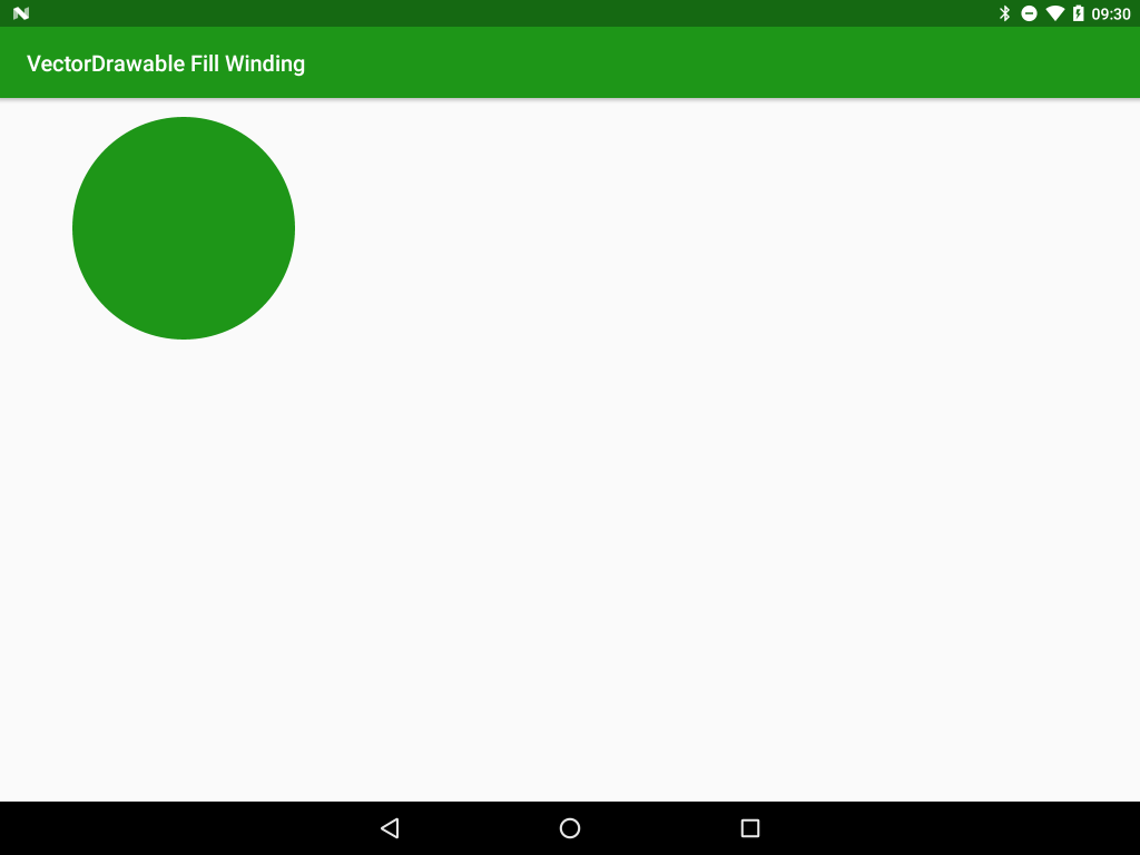
I opened the source SVG in Sketch (the same tool as the designers were using) and all looked good, and studied the SVG pathData itself and could see the inner circle within the path. So where did it go?
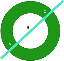
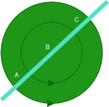
To understand what happened we need to understand how filled objects are actually rendered. There are two commonly used models (known as winding rules) for determining how an object should be filled. The first of these (and the easier to understand) is the even-odd winding. For any given pixel we draw an imaginary line to any edge of the canvas and count how many times we cross a path before we hit the edge. If the number is even the point is considered outside the path and is not filled; if the number is odd the point is considered inside the path and filled:
So, at point A, if we count along the line going up and to the left we cross the path 3 times – which is odd and so the pixel is inside the shape and gets filled.
At point B, if we count along the same line we cross the path twice – which is even and so the pixel is outside the shape and doesn’t get filled.
Point C is similar to point A – we cross the path an odd number of times so it is inside the path and it gets filled.
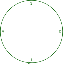
That’s easy enough to follow and if we apply that rule then we should get the cutout that we require. However the second winding model for calculating whether a pixel should be filled is actually a little more complex – but not that much. It depends on the direction in which a path is being drawn. If we consider the following circle which consists of four bezier curves with the points labelled 1, 2, 3, & 4:
The ordering of the points means that we’re drawing the circle in a counter-clockwise direction and this drawing direction is important for the second fill rule: the non-zero rule. For this we take the same approach of drawing an imaginary line to the edge of a canvas with a counter set to zero and each time we cross a path from left-to-right relative to our imaginary line we decrement our count; and each time we cross a path running in right-to-left relative to our imaginary line we increment our count. Once we reach the edge of the canvas, if the counter is zero it is considered outside the path and not filled; if it is not zero then it is considered inside the path and filled.
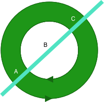
An example will explain this logic much better:
Here the inner circle is rendered in the opposite direction to the outer circle – note the arrows at the bottom of each circle which shows the direction.
From point A if we traverse the imaginary line towards the upper right: First we cross the inner circle path running right-to-left so increment the count (1); then we cross the inner circle path running left-to-right to decrement the count (0); then we cross the outer circle path running right-to-left so increment the count(1). As this value is non-zero the point is considered inside the path and gets filled.
From point B if we traverse the imaginary line towards the upper right: First we cross the inner circle path running left-to-right to decrement the count (-1); then we cross the outer circle path running right-to-left so increment the count(0). As this value is zero the point is considered outside the path and is not filled.
However if we reverse the direction of the inner circle then something rather different happens:
Point A gives the same net result because in both cases it crosses the inner circle twice with the path running in different directions – which cancels itself out.
However from point B if we traverse the imaginary line towards the upper right: First we cross the inner circle path running right-to-left to increment the count (1); then we cross the outer circle path running right-to-left so increment the count again (2). As this value is non-zero the point is considered inside the path and is filled.
So looking back at the source image, I found that the two circles were both being drawn in a counter-clockwise direction. If we render using the even-odd rule then we’ll see the cutout; but if we render using the non-zero rule then we’ll see a solid circle. It should be pretty clear what the problem is: Sketch is rendering things using the even-odd rule, and the VectorDrawable is getting rendered using the non-zero rule, and this is causing the disappearing hole.
There are actually a few ways that we can fix this. Firstly we can edit our VectorDrawable and specify that the path should be rendered using the even-odd rule rather than the default non-zero rule:
<vector xmlns:android="http://schemas.android.com/apk/res/android"
  android:width="202dp"
  android:height="205dp"
  android:viewportHeight="205.0"
  android:viewportWidth="202.0">
  <path
    android:fillColor="#FFFFFF"
    android:fillType="evenOdd"
    android:pathData="..." />
</vector>
On the face of it, that seems to be the perfect solution until we discover that the fillType attribute was only introduced in API 24 (Nougat). Prior to Nougat all VectorDrawbales are rendered using the non-zero rule even if we use VectorDrawableCompat.
A second mechanism that we can use is an online conversion utility which can automatically convert even-odd filled paths to being non-zero winding compatible by reversing the direction of paths where necessary – it should detect potential issues and prompt you to convert.
The final approach that we can use is a manual one – working closely with designers to teach them how non-zero windings work so that they can create paths in the correct direction so that they render correctly both when the even-odd and non-zero windings are applied. This is the approach we took once we understood the problem and I must give a massive hat tip to George Bevan and Tom Jay at ustwo for showing enormous patience as I requested frequent and sometimes rather bizarre changes to graphical assets during the process of understanding this issue – thanks guys!
The source code for this article is available here.
© 2016, Mark Allison. All rights reserved.
Copyright © 2016 Styling Android. All Rights Reserved.
Information about how to reuse or republish this work may be available at http://blog.stylingandroid.com/license-information.



Thanks for the article.
Just a minor type you have: “If the number is EVEN the point is considered outside the path and is not filled; if the number is EVEN the point is considered inside the path and filled:”
Well spotted. Thanks for pointing it out. It’s now fixed.
Wow! This explains exactly what was going wrong with the last few vector files I was using.
Thank you for giving such an easy to understand explanation.
I will definitely be sharing this info with my team.
Thank you SO MUCH!
I was driven crazy by Android studio refusing to build and complaining about
android:fillColor=”?attr/colorOnPrimary” being an invalid value which it is not!
the problem was indeed with the evenOdd filltype, and the online tool you provided worked perfectly.
Just don’t forget to check the box for “Fix fill type” of course
🙂