
Amazing things are possible with AnimatedVectorDrawable and regular readers of Styling Android will know that I’m a huge fan of them. Earlier this year I worked on a project for a UK TV broadcaster and produced an AnimatedVectorDrawable of the isometric company logo which went in to the app as an Easter Egg. Sadly I was unable to obtain permission to use the logo in question, but in this series of articles we’ll look at the entire process that I went through in order to create this animated logo.
 In the previous article we took a look at the structure of the pathData which made up one of the parallelograms in our graphic, in both the raised and flattened states. So now let’s look at how we can actually animate between those states.
An AnimatedVectorDrawable XML file is actually a mapping of objectAnimators to individual elements within a VectorDrawable definition. We can create an objectAnimator which will animate the pathData of one of our elements – specifically the south-west tile:
<animated-vector xmlns:android="http://schemas.android.com/apk/res/android"
  xmlns:aapt="http://schemas.android.com/aapt"
  xmlns:tools="http://schemas.android.com/tools"
  android:drawable="@drawable/raised"
  tools:ignore="MissingPrefix">

  <target android:name="south_west">

    <aapt:attr name="android:animation">

      <objectAnimator
        android:duration="1000"
        android:propertyName="pathData"
        android:repeatCount="infinite"
        android:repeatMode="reverse"
        android:valueFrom="M109.2,256L220.1,320L331.1,192L220.1,128Z"
        android:valueTo="M109.2,256L220.1,320L331.1,256L220.1,192Z"
        android:valueType="pathType" />

    </aapt:attr>
  </target>
</animated-vector>
At the top level we define the drawable that we are going to animate – in this case res/drawable/raised. We then specify a target which maps an animator to an individual named element. Remember when we named all of our path elements back in Part 1? We’ll this is why we needed to do that so that we can address them from within the AnimatedVectorDrawable in order to apply animations to them.
We then define the animation itself – we’re using AnimatedVectorDrawable Bundle format here. If you’re unfamiliar with it, we covered it recently on Styling Android.
The animation itself is an objectAnimator which allows us to change the value of a specific property of an object. The property that we’re going to change is the pathData attribute of the path element – this is specified in the propertyName attribute.
We then define valueFrom and valueTo which define the start and end states of the pathData. Those with a good memory will recognise these as the raised and flat states of the south-west tile which we dissected in the previous article.
We also need to specify a valueType of pathType so that the animator nows that it is manipulating pathData.
We also set standard attributes to reverse the animation once it completes, set the animation duration to 1000ms, and repeat the whole thing indefinitely.
The really clever bit is that the object animator will actually interpolate coordinate values between the start and end and produce a new pathData string for each frame of the animation at render-time – so all we need to do is give it the start end end paths and it will do the rest.
However, this is not without some caveats. Understanding how path data actually works is important here – and that’s why we covered it in detail in the previous article. The order, type and number of SVG commands is really important. If you compare the two paths, they are drawing the edges in exactly the same order, there are an identical number of commands, and each Command type matches that or the corresponding command at the same position:
| M109.2,256 | L220.1,320 | L331.1,192 | L220.1,128 | Z |
| M109.2,256 | L220.1,320 | L331.1,256 | L220.1,192 | Z |
| Moveto | Lineto | Lineto | Lineto | Closepath |
If we don’t match the types and numbers of the comm ands like this then we’ll get an error at runtime as the animator will not be able to correctly match the two lots of pathData.
What’s happening internally is really quite simple – the values of the X and Y coordinates are simply changed according to the position within the animation. For the third command, the Y coordinate at animation position 0.0 will be the same as the value from the valueFrom – 192, and at animation position 1.0 it will be 256. The values at animation points between 0.0 and 1.0 will be determined according to the Interpolator being applied, but if we assume a linear interpolator (for the sake of simplicity) then points in the middle will be calculated as a linear value between 192 and 256 depending on the animator position. In a nutshell: it will move the Y position of that vertex during the course of the animation – which is what we determined that we needed to do at the end of the previous article.
In order to see this in action we need tostart the animation:
public class MainActivity extends AppCompatActivity {

    @Override
    protected void onCreate(Bundle savedInstanceState) {
        super.onCreate(savedInstanceState);
        setContentView(R.layout.activity_main);

        startAnimation();
    }

    private void startAnimation() {
        ImageView imageView = (ImageView) findViewById(R.id.animated_image);
        if (imageView != null) {
            startImageViewAnimation(imageView);
        }
    }

    private void startImageViewAnimation(ImageView imageView) {
        Drawable drawable = imageView.getDrawable();
        if (drawable instanceof Animatable) {
            startAnimatableAnimation((Animatable) drawable);
        }
    }

    private void startAnimatableAnimation(Animatable animatable) {
        animatable.start();
    }
}
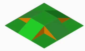
if we run this we can see our south-west tile animating between the raised and flattened states:

So with this knowledge we can apply the same technique of creating animators which transition between the raised and flat states to the north=west, north-east, south-east and centre tiles (I won’t include the full code here, but it’s available in the source):
That’s looking pretty good – and we’re actually seeing that the brown triangles are being animated yet we haven’t done anything to them. In the concluding article in this series we’ll look at what is going on with the brown triangles, and also apply a colour transition to some of the tiles.
The source code for this article is available here.
© 2016, Mark Allison. All rights reserved.
Copyright © 2016 Styling Android. All Rights Reserved.
Information about how to reuse or republish this work may be available at http://blog.stylingandroid.com/license-information.